Optocouplers, also known as optoisolators or photocouplers, have been used to achieve galvanic isolation in electronic circuits for more than 40 years. Optocouplers use an LED and phototransistor to enable signal communication without the transfer of current. Historically, optocouplers have been popular because they were a low-cost solution. However, given the advancements in digital isolation technology, are optocouplers really the most cost-effective method to achieve galvanic isolation for an RS-485 system?
Figure 1 shows a typical circuit for isolating an RS-485 transceiver using optocouplers to achieve galvanic isolation. A total of three optocouplers are required in this solution: two high-speed optocouplers (one each for transmit and receive signals) and a low-speed optocoupler for direction control. This solution will also require a significant amount of external components, including Schmitt buffers, a Schmitt trigger, resistors and bypass capacitors. All of these components can add up both in cost and board area.
Image may be NSFW.
Clik here to view.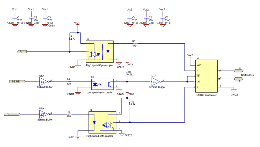
Figure 1: An isolated RS-485 design using optocouplers
Many system designers today across a variety of industrial markets are encountering issues with board-space constraints as they move toward smaller overall solution sizes or increased functionality with each new generation. One example of this is heating, ventilation and air-conditioning (HVAC) systems that regulate temperature and airflow in buildings. With the growing trend toward smart, energy-efficient buildings, new HVAC control boards need to be able to incorporate advanced monitoring and interface with smart thermostat systems without increasing the overall solution size.
Image may be NSFW.
Clik here to view.
Optimize your isolated RS-485 designs
| Image may be NSFW. Clik here to view. | Learn more about how to replace optocouplers in your isolated RS-485 designs by reading our application note "isolate RS-485 for smallest size and highest reliability". |
Image may be NSFW.
Clik here to view.
RS-485 is a common communication interface in these systems because of its reliability over long distances. When RS-485 nodes are placed at locations with different ground potentials, common-mode noise can cause communication errors, resulting in a need for isolation to prevent these ground-potential differences. Using a bulky optocoupler solution to isolate RS-485 can force designers to make compromises elsewhere in the system, driving the need for smaller isolated interface solutions.
In addition to the large solution size, many designers will also encounter these performance concerns with optocouplers:
- Reliability. Optocouplers will typically use epoxy as their dielectric; epoxy will break down at lower voltages compared to other common dielectrics, shown in Figure 2. Assembly inconsistencies and LED degradation will also cause device-to-device variations in terms of isolation reliability and lifetime.
Image may be NSFW.
Clik here to view.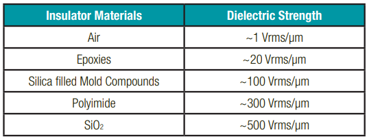
Figure 2: Dielectric strength of common insulator materials
- Power consumption: Each optocoupler requires 5-10 mA to drive the LED on the internal input die.
- Temperature range: Optocouplers are mostly limited to an 85°C maximum ambient temperature, with rare exceptions that are capable of as much as 105°C for a high premium.
- Switching specifications: Rise/fall time and propagation delay in optocouplers can vary depending on the biasing current, current transfer ratio and device-to-device variation.
- Noise immunity: Typical common-mode transient immunity for optocouplers ranges from 15 kV/µs to 25 kV/µs. In the presence of voltage transients above this level, data corruption is likely.
To meet the growing need for compact solutions without compromising performance, TI has created the ISO1500 isolated RS-485 transceiver. Figure 3 compares the solution size of the optocoupler solution shown in Figure 1, an industry-standard 16-pin small-outline integrated circuit (SOIC) isolated RS-485 transceiver and the ISO1500. Note that these designs only show the signal isolation of the RS-485 transceiver. The application note, “How to Isolate Signal and Power for an RS-485 System”, provides a helpful overview for isolating power in RS-485 systems.
Image may be NSFW.
Clik here to view.![]()
Figure 3: Solution size comparison between the optocoupler solution (a); an industry-standard 16-pin SOIC isolated RS-485 transceiver (b); and TI’s ISO1500 (c)
The ISO1500 reduces board space by as much as 85% compared to the discrete optocoupler solution and as much as 50% compared to the industry-standard 16-pin SOIC package. In addition to minimizing solution size, the ISO1500 also solves many of the performance concerns that I mentioned above. All TI isolated RS-485 transceivers are created in a semiconductor fabrication process using silicon dioxide as the dielectric to minimize device-to-device variation and provide more reliable high-voltage performance. The ISO1500 consumes <10 µA of current to drive the complementary metal-oxide semiconductor-based inputs, can be used from -40°C to 125°C, has predictable switching specifications, and showcases much higher noise immunity compared to a traditional optocoupler. When you combine these system-level benefits with the board-space savings that come with using the ISO1500, it becomes clear that the cost of an optocoupler adds up to significantly more than the price paid for just the device.
Additional resources
- Read the white paper, “Enabling high voltage signal isolation quality and reliability.”
- Watch the TI Training video series, “How High-Voltage Isolation Technology Works.”
Clik here to view.